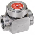
Thermal Disc Steam Traps
Operation
 Tunstall Corporation produces a full line of Thermal-Disc™ Steam Traps. Available in 3/8″, 1/2″, 3/4″ and 1″ NPT connections, all the internal parts are stainless steel for long service life.
The Tunstall Thermal-Disc™ operates using Bernoulli’s Theorem; as condensate enters the Thermal-Disc™ Trap, it lifts the thermal disc and discharges through outlet ports. Multiple outlet ports assure that the lift of the disc is parallel to the seat for efficient operation. Once the condensate reaches its flash point, the pressure on the top of the disc increases, due to higher velocity steam, causing the disc to snap closed. As the steam above the disc condenses, pressure above the disc will lower, and allow the disc to lift again and repeat the process.
Features
- In-Line Connection
- Integral Strainer
- Compact Size
- High Strength Stainless Steel Construction
- Low Maintenance (Only one moving part)
- Can be installed Vertically for “Freeze Proof” installation
Applications
- Steam Main Drainage
- High Pressure Drips
- Tracer Lines
- Process Equipment
- Laundry Equipment
- Kitchen Equipment
- Superheated Steam applications
- Outdoor installations subject to freezing
Construction
| Materials of Construction | |
| Body | Stainless Steel Casting ASTM A743 |
| Cap | Stainless Steel AISI 420 |
| Disc | Stainless Steel AISI 420 |
| Strainer Screen | Stainless Steel AISI 420 |
| Strainer Cap | Stainless Steel AISI 420 |
Specifications
PMA – Max. Allowable Pressure: 600 psi
TMA – Max. Allowable Temperature: 800° F
PMO – Max. Operating Pressure: 600 psi
TMO – Max. Operating Temperature: 800° F
Dimensions and Weights
| Model | Size | A | B | C | Weight |
| TA-TD-38 | 3/8″ | 3 | 1.75 | 2.5 | 1.6 |
| TA-TD-50 | 1/2″ | 3 | 1.75 | 2.5 | 1.8 |
| TA-TD-75 | 3/4″ | 3 | 1.75 | 3 | 2.4 |
| TA-TD-100 | 1″ | 3 | 1.75 | 3 | 2.6 |
Note: Dimensions in inches & Weights in pounds
Capacities – lbs. of condensate/hr
| Inlet (psig) | TA-TD-38 | TA-TD-50 | TA-TD-75 | TA-TD-100 |
| 3.5 | 180 | 300 | 415 | 650 |
| 5 | 185 | 315 | 430 | 680 |
| 10 | 190 | 350 | 475 | 740 |
| 15 | 195 | 380 | 520 | 815 |
| 20 | 200 | 415 | 565 | 885 |
| 25 | 215 | 440 | 610 | 940 |
| 30 | 220 | 470 | 650 | 1000 |
| 40 | 230 | 515 | 720 | 1080 |
| 50 | 250 | 580 | 825 | 1225 |
| 75 | 310 | 710 | 1020 | 1500 |
| 100 | 375 | 825 | 1185 | 1800 |
| 150 | 500 | 1020 | 1480 | 2215 |
| 200 | 620 | 1165 | 1710 | 2625 |
| 250 | 710 | 1300 | 1950 | 2935 |
| 300 | 800 | 1440 | 2110 | 3300 |
| 350 | 825 | 1565 | 2265 | 3600 |
| 400 | 900 | 1670 | 2490 | 3875 |
| 450 | 1070 | 1775 | 2625 | 4120 |
| 500 | 1120 | 1880 | 2780 | 4350 |
| 550 | 1185 | 1960 | 2985 | 4560 |
| 600 | 1290 | 2060 | 3140 | 4840 |
Note: Max. back pressure should not exceed 80% of the inlet pressure under any conditions of operation, otherwise the trap may not shut.
Installation
Valve installation is typically in the horizontal position as close to the equipment being drained as possible. A 20 mesh strainer is recommended upstream of the trap as is an isolation valve. Piping to and from the trap should be equal to the trap connection (one size larger is acceptable). Body material is not suitable for welding.
Freeze proof installation is achieved by installing the trap vertically, discharging downward. All drains must be pitched towards the trap. Discharge piping must be self-draining.
BULLETIN: Series-TA-TD-0814 – Thermal-Disc™ Steam Traps – Series TA-TD

